Pulsed Electromagnetic Field Therapy: Principles, Technology, and Practical Applications
Pulsed Electromagnetic Field (PEMF) technology applies controlled, time-varying electromagnetic fields to a defined target area. Originally developed in clinical and research environments, PEMF systems are now used across rehabilitation, wellness, and device development sectors.
This overview focuses on PEMF from a technical and system-level perspective, outlining how the fields are generated, how key parameters are defined, and what engineering considerations influence real-world performance.
1. What Is PEMF?
PEMF refers to electromagnetic fields that are intentionally pulsed rather than static or continuous. These fields are generated when an electric current flows through a coil in a controlled on–off sequence, causing the magnetic field to repeatedly expand and collapse.
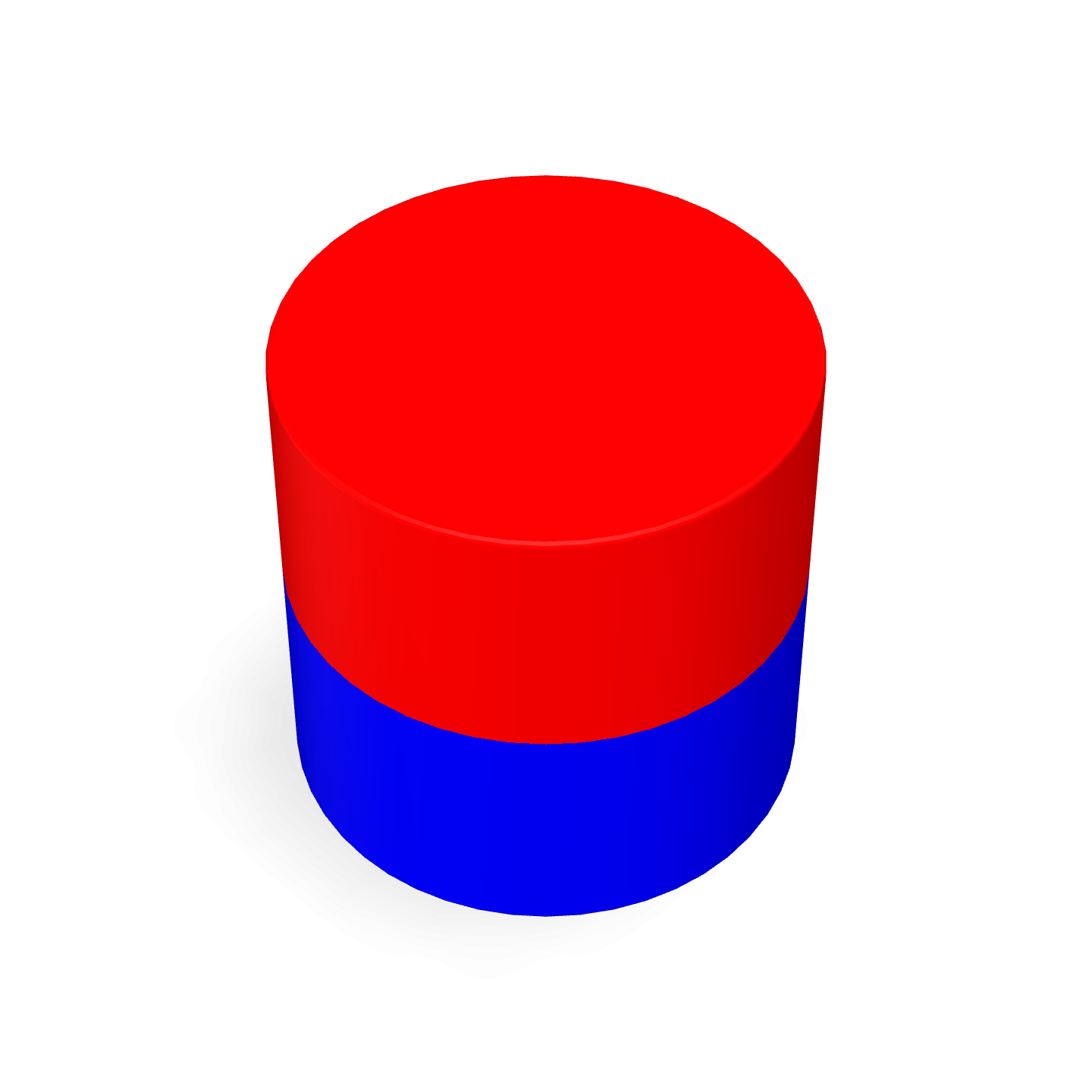
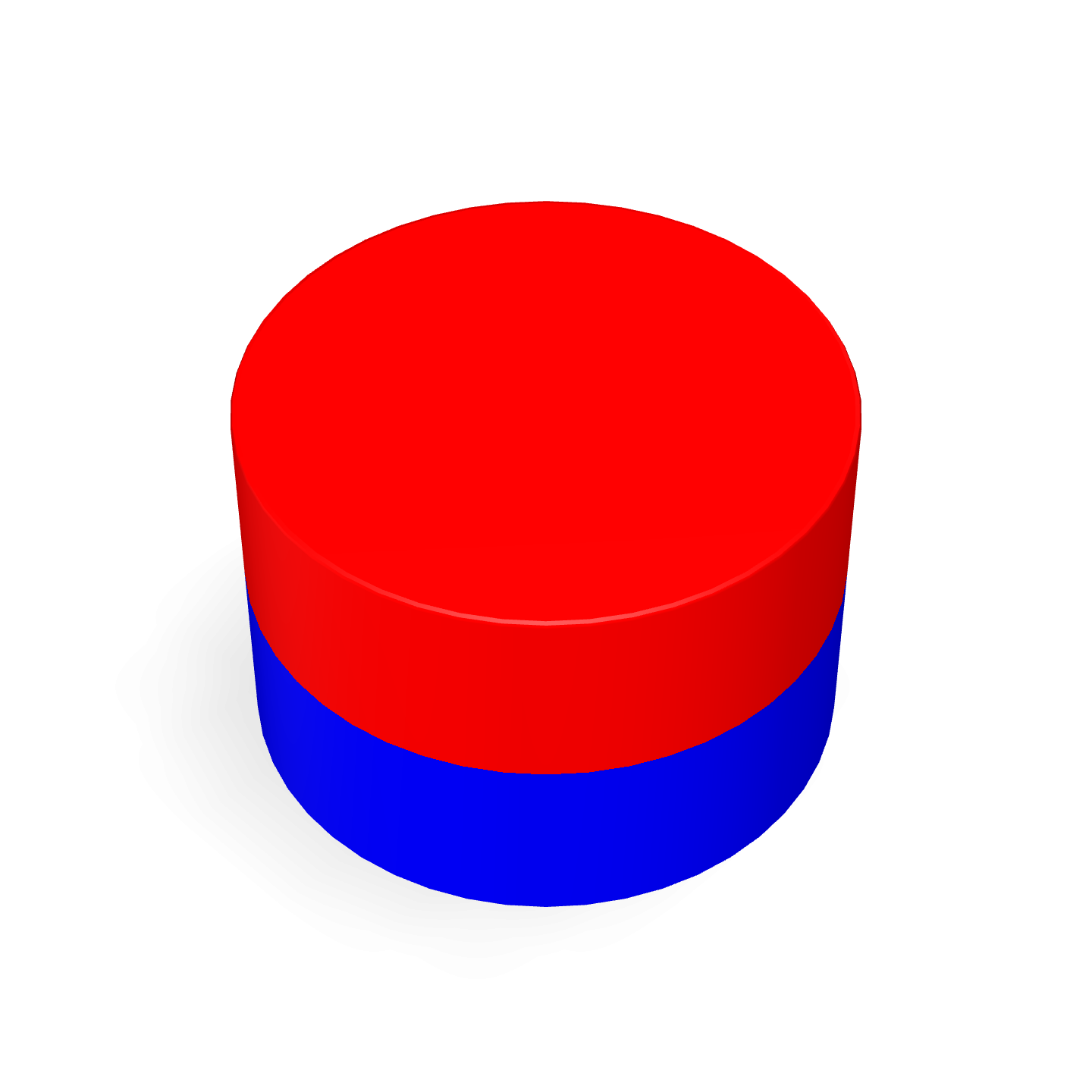
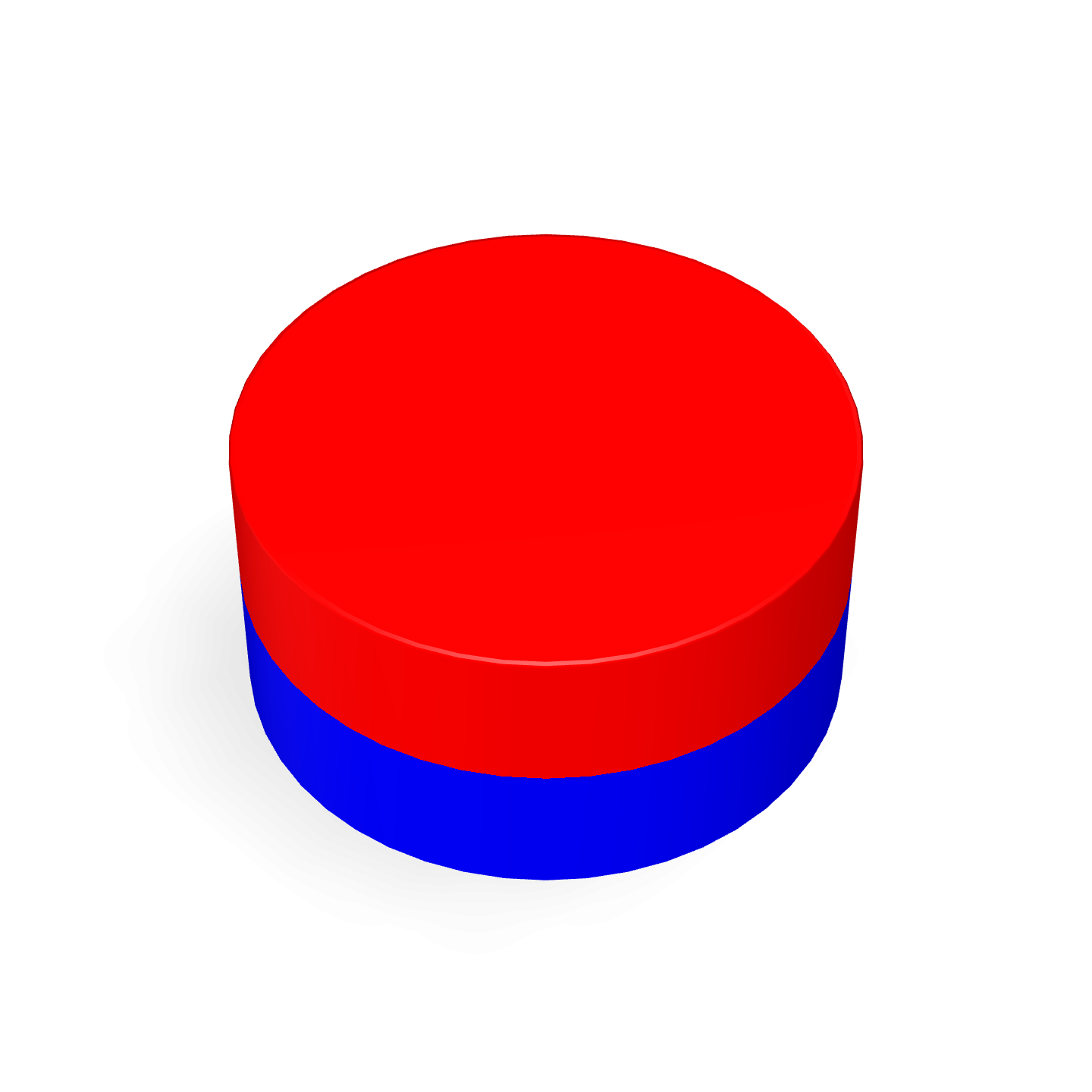
Unlike permanent magnets, which produce a constant magnetic field, PEMF systems rely on temporal variation. The behavior of the field over time — including pulse duration, repetition rate, and waveform shape — defines the system’s operating characteristics.
In practical terms, PEMF is best understood as a method of generating repeatable, programmable electromagnetic field cycles.
2. How PEMF Systems Generate Electromagnetic Fields
At the hardware level, PEMF systems operate using well-established electromagnetic principles:
- An electronic controller delivers a pulsed electrical current
- The current passes through a conductive coil
- A magnetic field forms around the coil
- The field collapses when the current is interrupted
This cycle repeats according to predefined timing parameters. Because the magnetic field is changing, small electric fields may be induced in nearby conductive materials, as described by Faraday’s law of electromagnetic induction.
From an engineering standpoint, PEMF devices are controlled electromagnetic field generators rather than static magnetic systems.
3. Core Components of a PEMF System
3.1 Coil Assembly
The coil is the primary field-generating element. Its design has a direct impact on field strength, spatial distribution, and thermal behavior. Key variables include:
- Number of turns
- Wire gauge and insulation
- Coil geometry (flat, solenoidal, or multi-coil configurations)
- Use of air-core or ferrite-core structures
3.2 Power Electronics
Power electronics regulate how current is delivered to the coil. Typical systems incorporate:
- Pulse-generation circuitry
- Switching components such as MOSFETs or IGBTs
- Current limiting, protection, and thermal safeguards
Stable current control is essential to maintaining consistent field output.
3.3 Control Unit
The control unit defines the operational parameters of the PEMF system, including:
- Pulse frequency
- Pulse width and repetition pattern
- Duty cycle
- Total operating time
These parameters are typically programmable, allowing the same hardware platform to support multiple operating modes.
3.4 Mechanical Housing
Mechanical design considerations include heat dissipation, electrical insulation, and electromagnetic compatibility. Enclosures must protect internal components while ensuring safe and reliable operation.
4. Waveforms and Operating Frequencies
PEMF systems use a range of waveform profiles, each producing a distinct time-dependent magnetic field:
- Square wave pulses with rapid transitions
- Sine wave signals with smooth field variation
- Triangular waveforms featuring linear ramps
- Custom or multi-phase waveforms designed for specific system goals
Operating frequencies commonly span from fractions of a hertz to several kilohertz. Field strength and frequency are independent variables; a higher frequency does not inherently imply a stronger magnetic field.
5. Magnetic Field Strength and Measurement
Magnetic field intensity in PEMF systems is typically specified in gauss (G) or tesla (T). Reported values may represent peak, average, or RMS measurements, depending on the measurement method.
Because PEMF fields are dynamic, accurate measurement requires attention to:
- Sensor placement relative to the coil
- Timing of measurements within the pulse cycle
- Distance from the field source
Measurement results can vary significantly if these factors are not controlled.
6. Engineering and Design Considerations
Designing a PEMF system involves balancing multiple engineering constraints, including:
- Thermal management of coils and electronics
- Electrical efficiency and power consumption
- Field consistency across the intended target area
- Mechanical robustness and long-term reliability
- Minimization of electromagnetic interference
Coil heating, insulation degradation, and component fatigue are common design challenges, particularly in systems operating at higher duty cycles.
7. Regulatory and Compliance Considerations
Depending on jurisdiction and intended use, PEMF systems may be subject to electrical safety standards, electromagnetic compatibility requirements, and product labeling regulations.
Early consideration of compliance requirements can reduce redesign risk and streamline certification later in the development process.
8. Summary
PEMF technology is based on the controlled generation of time-varying electromagnetic fields using pulsed electrical currents. System performance depends on waveform definition, coil design, power electronics, and thermal management.
A disciplined engineering approach ensures predictable field behavior, repeatable operation, and long-term system reliability.
Next Step: Request technical specifications or electromagnetic field calculations to support your PEMF system design.
Disclaimer: This content is provided for technical and informational purposes only and does not make medical or therapeutic claims.